Mechanical Design
The Fila-bust-a-move Robot is an autonomous sumo wrestling robot built for pushing power!.
To successfully win a wrestling match, the robot weighs the maximum amount, 15lbs, and its design prioritizes high traction and torque over speed an maneuverability. Four independently-driven wheels are coupled directly to 100:1 gear ratio DC motors. The motors were purchased from Jameco for ease of access and potential replacement. Of the available DC motor selection, we chose the motors with highest torque of with rpm high enough to move the robot across the playing field within 30 seconds (before the sequester started moving), assuming 3" diameter wheels. High traction rubber tread, mounted over 2.5" diameter longboard wheels provided a high friction interface to the ground. The armored chassis combined steel bolts, laser-cut duron, and clear acrylic in a low-profile "bull-dozer geometry " with a compound-eye perched above at the altitude of the opponent's beacon.
To successfully win a wrestling match, the robot weighs the maximum amount, 15lbs, and its design prioritizes high traction and torque over speed an maneuverability. Four independently-driven wheels are coupled directly to 100:1 gear ratio DC motors. The motors were purchased from Jameco for ease of access and potential replacement. Of the available DC motor selection, we chose the motors with highest torque of with rpm high enough to move the robot across the playing field within 30 seconds (before the sequester started moving), assuming 3" diameter wheels. High traction rubber tread, mounted over 2.5" diameter longboard wheels provided a high friction interface to the ground. The armored chassis combined steel bolts, laser-cut duron, and clear acrylic in a low-profile "bull-dozer geometry " with a compound-eye perched above at the altitude of the opponent's beacon.
Quick Specifications:
- 4 wheel drive (One 3.2 Nm torque motor per wheel)
- Weight : 15.0 lbs (maximum allowable competition weight)
- Dimensions: 11"x11"x11"
- Gear train: 38GM Series 100:1 Reversible Gear Head (50 rpm output)
- Motors: 4 x 3.2 Nm torque at max efficiency DC Motors (JAMECO 253518), 72 rpm no load speed , 12V DC operating voltage, 300mA stall current.
- Wheels: 4 longboard wheels, 2.5" diameter, 2" wide, with mounted tread.
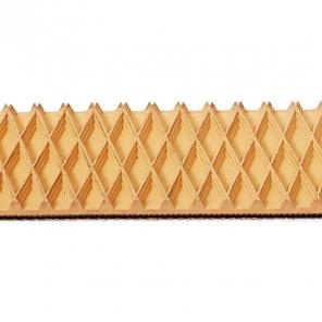
- Tread : Vex Robotics Wedge-Top Traction Tread.
Chassis
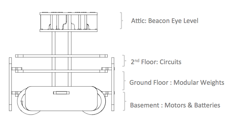
The chassis comprises of 4 layers :
- A Basement: houses wheels, motors, and two 7.4V rechargeable NiCad batteries.
- The Ground Floor: a weight layer with two 3 pound dumbbells for a low center of gravity and to hit the maximum weight limit.
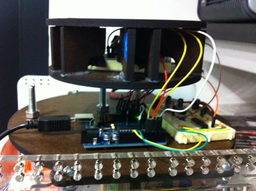
- The 2nd Floor: electronic substems
- The Attic: A beacon sensor platform with multiple slits for IR beacon sensing and roof for mounting the class-standard beacon transmitter.
|
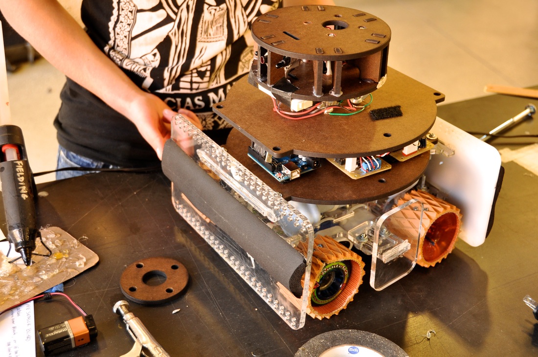
The side view of the robot is shown here illustrating the layout of chassis in relation to the other subsystems.
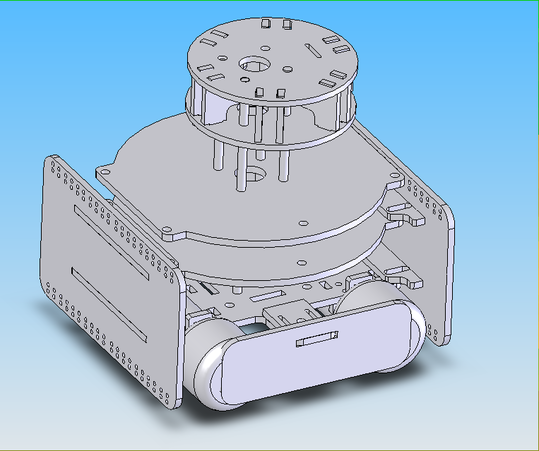
All sides of the robot are protected by vertical 1/4" acrylic walls with soft foam bumpers for protection. 3D CAD modeling software (Solidworks) was used to design the layout of all mechanical systems. |
|
|
The front and back bumpers have an array of mounting holes for additional sensors. Tape sensors were mounted to the bumper in each corner of the robot and can be adjusted in height by using different hole positions.
The bumpers have slotteds holes in their mounting brackets that allowed some flexibility in adjusting the overall length of the robot. Bump sensing is a feasible addition to this design by coupling to the displacement of the bumpers. The Full CAD Model of Fill-a-Bust-Move can be found here :
|
||
FabRICATION And ASSEMBLY
Fabrication of the CAD design used 2D laser cutting to rapidly prototype the planar structual components of the robot. An exploded view of the parts in the assembly is shown below. For parts requiring higher rigidity and strength, such as the base plate of the wheel mountings, 1/4" clear Acrylic is used. Internal platforms with low strength requirements use 1/4" Duron. The overall structure is held in place with a standard set of steel fasteners , with wing nuts in places that require frequent dissasembly. 4 Vertical carriage bolt fix the beacon sensing eye over the chassis and add rigidity to the structure.
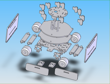
Exploded view of final design
|
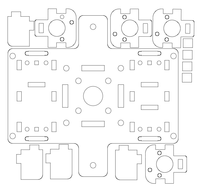
Laser cut Baseplate for motor mounting brackets.
|
motor Selection
Motors were selected primarily based of the highest torque, reasonable rpm ( >4) motors that could be obtained locally (namely at Jameco).
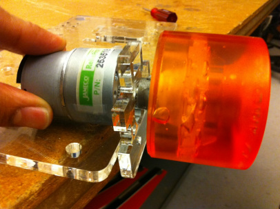
The specification sheet of the selected motor can be found here: Jameco 253518 12V DCMotor ($17.95)
The specification sheet of the selected motor can be found here: Jameco 253518 12V DCMotor ($17.95)
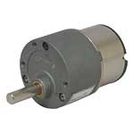
Jameco DC motor 253518.
|
Initial back-of-the-envelop calculations for choosing our motors:
Assumptions for our robot: 4 wheels, 3" diameter 4 motors mass = 15lb = 6.8 [kg] Coefficient of static friction, mu = 1 (~Rubber on plastic) Normal force, Fn = mass * g = 67N To traverse the playing field in 30 sec: minimum robot linear vel = 96 inches/30 sec omega_wheels = minRobotVel / (2*pi*wheel radius) = 3.24 rev/min for 3" diam wheels. Minimum torque to move itself without opponent: T = mu * Fn * wheel radius = 1 * 67[N] * 0.0381[m] = 2.55 [Nm] Assuming 4 motors, T = 2.55[Nm]/ 4 = 0.635 [Nm] per motor Torque to push only the brick: We're told 0.5 to .75 lbs force is required to push the brick. Let's take 1[lbf] to be safe. 1lbforce = 4.48 Newtons T = F * wheel radius = 0.171 [Nm] for all 4 motors = 0.0426 [Nm] per motor Maximum Torque at Maximum Efficiency: (assuming 2 motors) ("To avoid wheel slippage") = (Fn*Radius*mu) / 2 motors, where mu = 1 = 1.27 [Nm] per motor (These are larger values than the motors we've been looking at, so we're good.) How fast will we move? With motor shaft at 40 rpm(Jameco 253518): Linear velocity = circumference * angular velocity = 2*pi*radius*40 [rev/min]*(1/60 [min/sec])*(2*pi [rad/min]) = 1.0027[m/s] The playing field is 96" long, or 2.4[m], so at 40rpm we can expect to traverse the field in roughly 2.4 seconds. Based on these specifications we chose to use four Jameco 253518 12V DC motors. |
Wheel Assembly
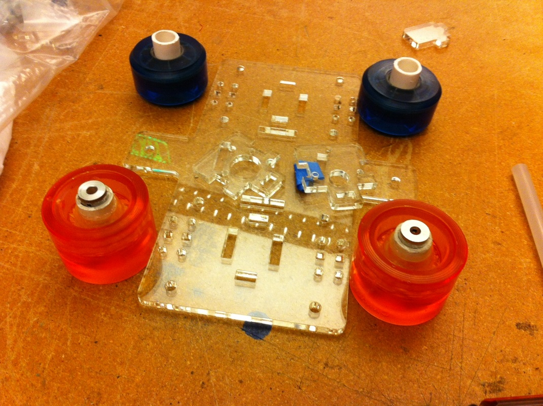
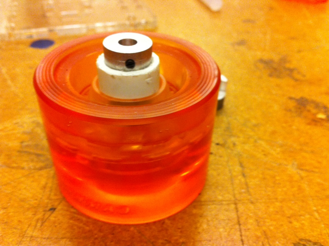
The wheels in the final design are 4 longboard wheels 2.5" in diameter and approximately 2" width. The wheels were selected based on 1. Local availability 2. Low durometer 3. High friction surface over a broad area to allow for a more robust point of contact to the ground.
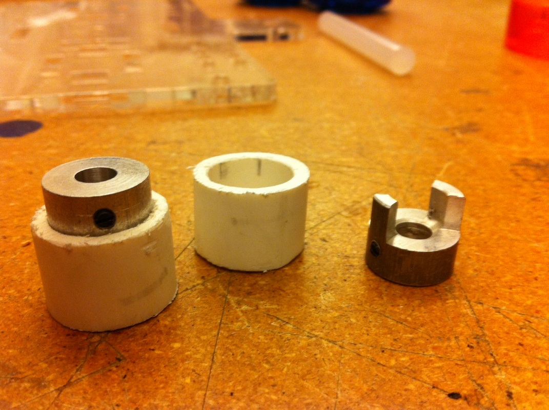
Wheels are mounted to the motor shaft through a PVC + aluminum spider coupler. The PVC diameter fits snuggly into the standard hole intended for bearing inserts. A set-screw based spider coupler is then press fit and glued into the inner diameter of the PVC coupling. PVC Cement was used to reinforce the press fit. The wheel can then be attached to the motor shafts by inserting the motor shaft out the gearhead and securing the set screw. The selected motors have an attached gearbox with a 1cm bronze bushing at the output and was found to be sufficient constraint for this robot's weight.
Tip: Black Diamond Sports in Downtown Palo Alto has a box of affordable "scrap" wheels sold at a healthy discount. The owner remarked "its that time of year again... everyone wants scrap long board wheels today for some reason..."
|
The wheel assembly is held in place by mounting the motors to vertical mounting plates constrained in the base plate.
Earlier versions of the design used alternative wheels with a chain and sprocket based drive train, but a heart breaking notice from UPS notified us that our wheels had been lost in the mail forcing us to redesign with more locally available skate shop wheels (Dreaded message: "An exception on the sorting process has occured. UPS has taken corrective action."). |
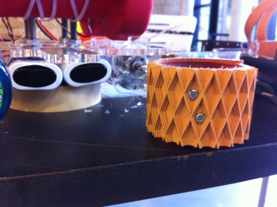
Traction
Vex Robotics Wedge-Top Traction Tread was used to augment the wheel friction with the ground. The tread is attached to the wheel by screwing 1cm wood screws directly into the longboard wheels. We found the resulting traction of the wheels to be significantly enhanced over the bare long board wheel material. The compliance the cross-hatched ribs maintained good contact with the ground, particularly when loaded with weight over 10lbs.
The tread can be purchased directly from Vex Robotics at this link: Vex 2" Wedgetop Traction Thread
The tread can be purchased directly from Vex Robotics at this link: Vex 2" Wedgetop Traction Thread
|
|
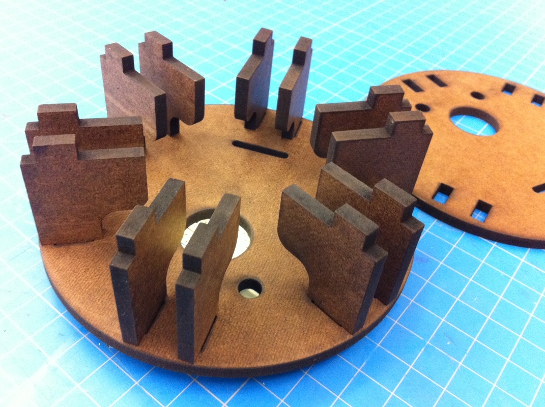
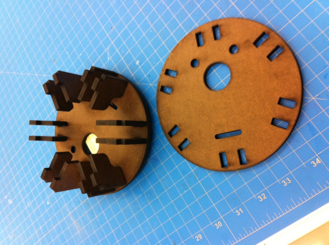
Beacon EYE
The beacon sensing eye is mounted at the top of the robot. It features radial narrow slits to look in multiple directions at once for sensing the location of the opposing robot. Narrow slits were preferred over wider "catch all" to get a more precise angular reading. Tall slits were preferred to account for variations in height of the incoming signal. Opaque duron material was used to prevent IR light from passing through to multiple photo diodes.